What do the following things have in common?
- Coherent light
- A girl’s makeup compact
- Tape recorder parts
- A willful imagination
Part 1:
LASER – Light Amplification by Stimulated Emission of Radiation. What an amazing acronym (cue bored yawns from ya’ll, as this stuff has been around for years and years). But it still excites me to think about it, so bear with me…
Way back in the late 1970’s, I was a teenager consumed by progressive rock music, sound systems and theatrical lighting. And I think you’ll agree, it was the greatest of times. Rock music was in it’s heyday.
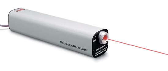
In those days, I was profoundly impressed by the Lasers that were starting to be used at rock concerts and at the Hayden Planetarium (the show was called Laserium). Somehow, I had to get one of these things and start experimenting to develop special effects for use in my own rock bands. A used Metrologic Laser was acquired that used Helium and Neon as the active illuminating gasses. When excited by a high voltage, the visible radiant emission of Neon could be used to create a coherent beam of bright red light. This thing was cool.
Part 2:
- Light Dances On Speaker Cones
- Etherial Aluminum Foil Clouds
Experimentation proceeded at a very rapid pace and a great deal was learned about lasers in a very short amount of time. One of my more inspiring moments came when I glued a mirror onto a speaker cone, aimed the laser at it and watched the reflected beam dance to the music in one axis. If I could aim the reflection at another mirror mounted to a different speaker, the reflected light beam would then show up as a two dimensional projection of fast moving audio waves. This was the basis of what I wanted to create, but this technique was clunky and totally unmanageable. More on the solution to this problem later.
As an aside, I found that I could produce the most amazing wispy clouds of laser light on the ceiling using slightly wrinkled aluminum foil, turning on a clock drive. The clouds it produced were etherial, magical and quite beautiful as Pink Floyd or Yes played in the background. The possibilities seemed endless.
Part 3:
- A Big Problem With Mirrors
As experimentation progressed, I discovered to my great dismay that glass mirrors have a big problem. The actual reflective material is deposited on the backside of a mirror’s pane of glass. So, the beam reflects off the front surface of the glass and also off the back of the glass, causing a doubling or blurring of the beam spot on the target screen. It only gets worse with distance. This was a big problem.
So I searched the world over, firing my beam at every mirror I could find in the house and looking at the quality of the reflected light. And I found that my sister’s makeup compact had a very thin glass mirror and it worked better by far than anything else. Eureka! (A huge shout out to both of my sisters) I don’t know what kind of deal I had to make but one of them gave me her compact and the rest is history. Eventually I learned that all laser optics uses specialized First Surface Mirrors to avoid this problem.

Part 4:
- How To Control A Laser Beam
This special effects laser display had to respond/dance to the music using audio signals. As mentioned in part 2, I tested mirrors on speaker cones but a better solution was required.
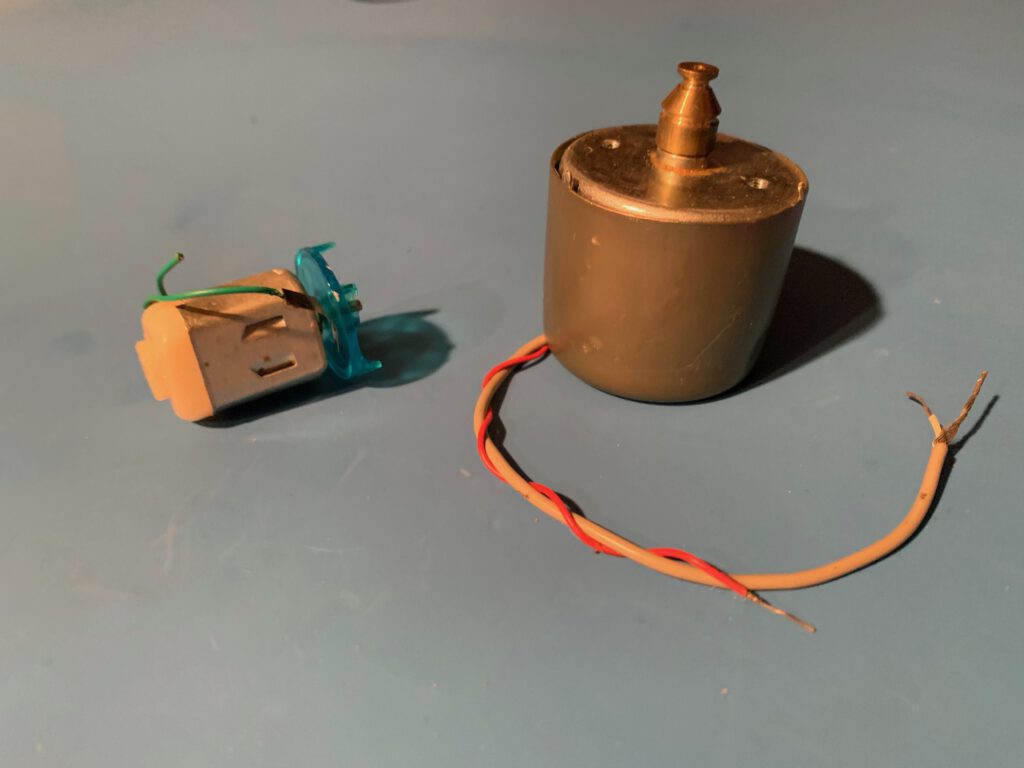
And the solution to that goal was to mount the mirrors onto the shafts of small motors. Since motors are similar to speakers (converting electrical signals to physical movement) I just needed to find the most precision motors available. In the attached photo, a crude motor is shown on the left and a precision motor on the right. These kind of precision motors are found in cassette tape recorders (a huge shoutout to my friend Paul who gave me his old Norelco tape deck for parts). You can see that the motor is encased so as to be protected from dirt/dust, it has many magnetic poles inside which make it run smooth and the bearings are tight and vibration free. Alternating analog signals are fed into the motor’s power wires, causing the shaft to move back and forth instead of spinning. I called them scanners. And now the only thing needed is a nice mount for a mirror.
Part 5:
- Exacto Knife Mirror Mounts
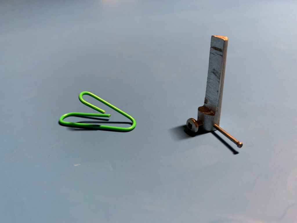
In the photo below, a pair of mirror mounts were fashioned out of the aluminum handle of an Exacto Knife. Holes were drilled for the motor shaft, set screw and a limiter bar (a tiny nail). This was no small feat using only a hand drill and patience. My sister’s compact mirror was unceremoniously ripped from it’s case, divided up, cut to size and mounted with silicon glue. Note that the mirror is missing because it was moved to a much improved mount that was made in my friend Bob’s machine shop.
Part 6:
- The Optical Scanner Assembly
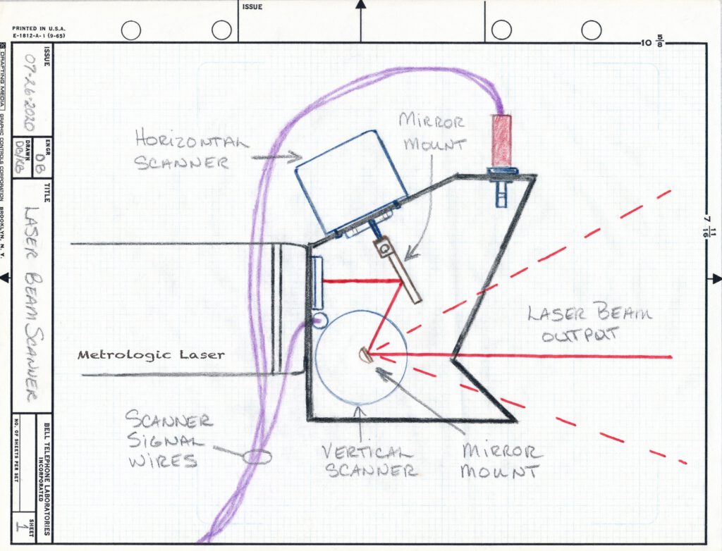
All of this work culminated in the creation of the device in the sketch below. One day I sat at my workbench with all the parts and a piece of perforated metal grating. A couple hours of work and poof, out came this Optical Scanner Assembly. I had no drawing, just a vague idea. It’s got both horizontal and vertical scan motors and the whole thing mounts on the laser’s aperture assembly.
Kathy and I drew up this sketch just the other day (45 years too late) so you could see how the beam bounces back and forth on the mirrors. What is not shown is the limiter bar that sticks out the side of each mirror mount. Once I positioned and centered the beam (by rotating the position of the mirrors), a bit of silicon glue was applied to keep the beam aimed in the desired direction. To my knowledge, nobody has ever developed an equivalent compact and practical device like this. It’s certainly unique.
Part 7:
LCU – Laser Control Unit
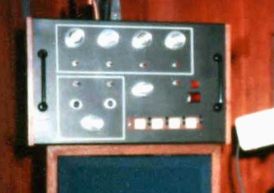
I built this unit from scratch, installing all the electronics into a beautiful wooden cabinet formerly occupied by the Norelco Cassette Deck mentioned above (another shoutout to my friend Paul). The front panel was made of steel. You won’t have to remind me to never use heavy steel plating again, it was hard to work with and ruined all of my Dads drill bits and saw blades (thanks and sorry Dad).
The LCU included two function generators, frequency, phase & level controls, programmable “accent” buttons (for instantaneous pattern changes), stereo inputs for musical audio signals, I/O for storing pre-programmed pattern sequences on a tape deck, two motor power amplifiers and a power supply.
Apologies for the blurry image below, I never took a decent photo of the darn thing.
Part 8:
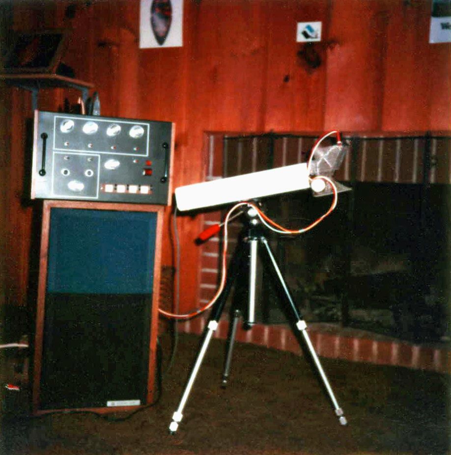
- Presenting the complete Laser Scanner System
In this photo the Laser stands on a tripod with a pan-tilt mount but I also fabricated a “U” bracket so it could hang from theatrical pipe grid in front of the stage, shooting bright laser beam patterns onto folding screen behind the band. The LCU could be set up in the back of the venue by the sound and lighting control positions. The only signal connections required to the scanner head (Horizontal, Vertical, Ground) could be routed through a heavy duty 3 prong extension cord of any length. Perfecto!
The patterns that can be created by the system include Lissajous patterns, star images, dancing waveforms and other unusual pyschedelic traces. The photo below is a time exposure from a Polaroid camera and only partially represents its capabilities.

Part 9:
- How I lost it
After I got my professional career off the ground at Bell Laboratories, I felt I could build a system that was ten times better. My prototype was just a profit center waiting to be cashed in. So I sold it. Yep, I sold it to someone I don’t know and I’ve never seen it again. All I have is the attached photos, one mirror mount and some vague memories. “Ouch”: This is the sound that I make as I continue to kick my self in the backside whenever I think about it.
And now you know all about the best piece of theatrical technology that I’ve ever designed and built (and lost). Stay tuned for future endeavors.